計装空気(Instrument Air)は、プラントにおける「神経系」です。電気信号が脳からの指令だとすれば、IAは筋肉であるバルブを動かすための動力源そのものです。
本記事では、たかが空気と侮られがちなIA設備の、設計思想から配管スペック(Pipe Class)、そして定検工事(SDM)における重大な注意事項まで、現場監督や設計者の皆様が知っておくべき知識を体系的に解説します。
プラントの安定稼働は、皆様のIA配管の品質にかかっていると言っても過言ではありません。
透明な血液、計装空気
プラント内には無数の配管が走っていますが、皆様は「最も重要なユーティリティは何か?」と問われたら何と答えるでしょうか。蒸気でしょうか、冷却水でしょうか。
私は迷わず「計装空気(Instrument Air、以下IA)」と答えます。
プロセス流体が「製品」なら、IAはプラントの意思を伝達する「血液」や「神経」です。たとえ停電しても、非常用発電機が回るまでの間、あるいはプラントを安全に緊急停止させる最後の瞬間まで、コントロールバルブを動かし続けなければならないのがIAです。
IAが止まれば、プラントは即座に制御不能(トリップ)に陥ります。だからこそ、我々はIA設備に対して異常なまでの執着を持って設計し、維持管理を行っています。
図面やスペックの裏側にある「意図」と、現場で実際に起こりうるトラブルの芽についてお話しします。
計装空気と雑用空気、その決定的な違い
まず基本の「キ」ですが、同じ空気配管でも、Utility Air(UA)やService Air(SA)と呼ばれる雑用空気と、IAは似て非なるものです。
敵は「水分」と「油分」
IAに求められる品質は、極めて厳格です。
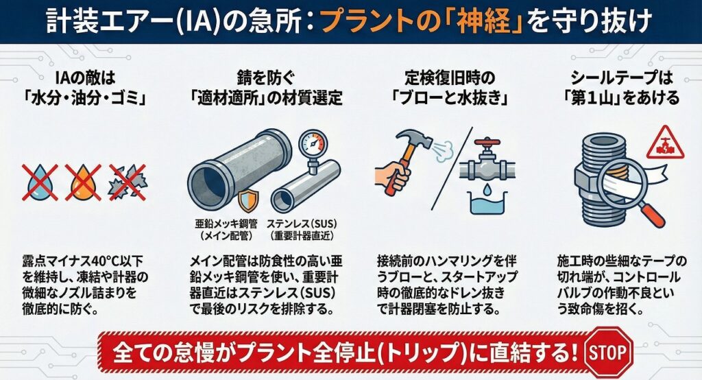
除湿(Dew Point): 大気圧下換算でマイナス40℃以下(冬場の凍結防止と錆防止)
オイルフリー: 油分を含まないこと(ポジショナー等の精密機器保護)
ダストフリー: 固形異物がないこと
もし、IAの中に水分が含まれていたらどうなるでしょう?
冬場、北風に晒された細い銅管(チュービング)の中で水分が凍結します。すると、空気の通り道が塞がれ、コントロールバルブが動かなくなります。
あるいは、配管内部から発生した錆の粉が、電空変換器(I/P)の微細なノズルを詰まらせます。 これらはすべて、プラントの緊急停止に直結します。
配管スペック(Pipe Class)に込められた設計思想
設計担当の皆様が図面を引く際、あるいは監督の皆様が材料検査をする際、IA配管のスペックを見て「なぜこの材料なのか」を考えたことはあるでしょうか。
なぜ亜鉛メッキ鋼管(Galvanized)なのか
一般的に、IAのメイン配管には「白ガス管(SGP-W)」や「スケジュール管の亜鉛メッキ品(STPG-W等)」が使用されます。 これには明確な理由があります。
防食性: 内面からの錆を防ぐため。IAは乾燥しているとはいえ、長年の使用やトラブル時の水分混入リスクを考慮し、炭素鋼(黒管)は使いません。
コスト: 全てをステンレス(SUS)にすれば錆びませんが、広大なプラント全体に敷設するにはコストが見合いません。
ただし、コントロールバルブ直近の配管や、重要な計器周りにはSUSを使用するケースが増えています。これは、バルブへ入る直前で最後の錆のリスクを排除するためです。
設計図面でClass break(スペックの変わり目)がある場合は、その位置に意図がありますので絶対に見落とさないでください。
接続方法の選定基準(ねじ込み vs 溶接)
2インチ(50A)以下: 一般的にねじ込み接合(Screwed)
3インチ(80A)以上: 溶接またはフランジ接合
ここで設計上のジレンマがあります。 ねじ込み配管は施工が早いですが、「漏れ」のリスクが常に付きまといます。
IAは圧力変動が少ないとはいえ、振動には弱い。 一方、亜鉛メッキ管は溶接するとメッキが飛び、そこから錆びるため、基本的に溶接は避けます(溶接する場合は、後の補修塗装が非常に重要、あるいはフランジ接続などを多用する)。
皆様にお願いしたいのは、「ねじ切り加工の品質」と「シールテープ・ヘルメチックの施工品質」です。ここが甘いと、数年後に必ずエア漏れが発生し、省エネロスだけでなく、圧力低下による操業トラブルを招きます。
設計条件(Design Conditions)の背景
IAシステムの設計条件は、概ね以下のようになっています。
供給圧力: 0.5 ~ 0.7 MPaG
※多くのコントロールバルブのアクチュエータは、0.4 MPaG程度で作動するように設計されています。配管圧損を見込んで、源圧は高めに設定されます。
設計圧力: 0.9 ~ 1.0 MPaG程度(設備による)
バックアップ: 窒素(N2)ガス
最後の砦、N2バックアップ
コンプレッサーが全台トリップした場合、IAヘッダーの圧力が下がります。そのままでは全バルブが死んでしまうため、圧力が一定値(例えば0.45 MPaG)まで下がると、自動的に高圧のN2ラインからIAラインへ窒素が供給されるシステム(PCV)が組まれています。
定検工事でIAラインの気密テストやパージを行う際、この「N2との縁切り」が確実にできているかを確認してください。
知らぬ間にN2が逆流していた、あるいはIAをN2側に混入させてしまった、という事例は過去に存在します。
定検工事(SDM)における「急所」と注意事項
現場監督の皆様、特に以下の点には目を光らせてください。私が冷や汗をかいた経験に基づく「急所」です。
1. 既設配管の「内部剥離」と「閉塞」
改造工事で既設の亜鉛メッキ配管を切り回す際、外観が綺麗でも、内部で亜鉛メッキが剥離しかけていたり、粉状の錆が溜まっていることがあります。
注意点: 新設配管を接続する際、既設管への振動や衝撃で内部のゴミが舞い上がり、下流の計器を詰まらせることがあります。
対策: タイイン(接続)前に、既設管のブロー(Air Blow)を徹底してください。ただ空気を流すだけでなく、木ハンマー等で軽く叩き(ハンマリング)、内部の異物を出し切ることが重要です。
2. 「水切り」の徹底
定検中は、IAコンプレッサーを止めて仮設コンプレッサーに切り替えたり、一部区間を開放したりします。この時、湿気を含んだ外気が配管内に入ります。 復旧時、この水分がドレンとなって滞留します。
注意点: 通気開始直後、末端のドレン抜きを怠ると、一気に大量の水が重要計器へ流れ込みます。
対策: 配管のポケット部(低い部分)には必ずドレン弁を設け、スタートアップ時は「これでもか」というほど水抜きを行ってください。
3. 誤切断の恐怖
IA配管は、プロセス配管に比べて小口径であり、足場材や他の配管の陰に隠れていることが多いです。また、電気計装のケーブルダクトと並走していることもあります。
注意点: 撤去工事の際、生きている(加圧中の)IAチューブや、バックアップ用のN2ラインを誤って切断する事故。
対策: 「ラインのトレース(追跡)」は、設計図面だけでなく、必ず現地で指差し確認を行ってください。特に、保温材が巻かれている場合や、塗装色が似ている場合は要注意です。マーキングは過剰なほどに行って損はありません。
4. シールテープの「切れ端」
ねじ込み配管の施工時、シールテープの巻き方が悪いと、切れ端が配管内部にはみ出します。 これが風に乗ってバルブのポジショナーに到達すると、致命的な作動不良を引き起こします。
対策: ネジの第1山にはシールテープを巻かない。これは鉄則ですが、新人職人さんが入る場合は、必ず教育と実演を行ってください。
主要機器についての豆知識
設計者の皆様向けに、機器周りの配置設計(レイアウト)のポイントを少し。
エアドライヤー(Air Dryer)
IAの品質を決める心臓部です。通常、吸着剤(活性アルミナやモレキュラーシーブ)を使用し、2塔を交互に切り替えて除湿します。
レイアウトの急所: 吸着剤の交換作業スペースを確保していますか? 重機が入れるか、あるいはマンパワーで運び出せる動線があるか。ここが考慮されていないと、数年後のメンテナンス部隊が泣くことになります。
エアレシーバー(Air Receiver)
バッファタンクです。
レイアウトの急所: ドレン抜きは最下部にあります。冬場、ここが最も凍結しやすい。ドレン弁へのアクセスは容易か、凍結防止のヒートトレースや保温の施工スペースはあるかを確認してください。
見えない空気への誇り
IA設備がいかに繊細で、かつプラントにとって重要か、お分かりいただけたでしょうか。
たかが空気、されど空気。 皆様が施工する一本のねじ込み配管、皆様が引く一本の配管ルート図面が、次の4年間のプラントの連続運転を支えます。
もしIAが止まれば、数億円、数十億円の損失が出るだけでなく、高圧ガス保安法に関わる重大な事故に繋がる可能性すらあります。
皆様の確実な仕事は、目に見えない空気の流れとなって、プラントの隅々のバルブまで届き、安全を守り続けます。
Instrument Air (IA): Role, Specifications, and Precautions
Instrument air is the "nervous system" of a plant. If electrical signals are the commands from the brain, then IA is the power source that moves the valves, which are the muscles.
This article systematically explains the essential knowledge that site supervisors and designers should know about IA equipment, which is often underestimated as merely air, from its design philosophy to piping specifications (Pipe Class) and important points to note during scheduled maintenance work (SDM).
It is no exaggeration to say that the stable operation of the plant depends on the quality of your IA piping.
Transparent blood, instrumentation air
There are countless pipes running through the plant, but if you were asked, "What is the most important utility?", what would you answer? Steam? Cooling water?
I would answer without hesitation, "Instrument Air (IA)."
If process fluids are the "product," then industrial air conditioning (IA) is the "blood" or "nerves" that communicates the plant's intentions. Even in the event of a power outage, IA must keep the control valves running until the emergency generators kick in, or until the very last moment the plant can be safely shut down.
If the IA (Integrated Air) system stops, the plant will immediately become uncontrollable (trip). That's why we design and maintain our IA equipment with an almost obsessive level of dedication.
I will discuss the "intentions" behind drawings and specifications, and the potential problems that can actually occur on-site.
The crucial difference between instrumentation air and general-purpose air
First, let's start with the basics: even though they're both air piping, utility air (UA) and service air (SA), which are used for general purposes, are similar to but not the same as air intake air (IA).
The enemies are "moisture" and "oil".
The quality standards required for IA (Information Architecture) are extremely stringent.
Dehumidification (Dew Point): Below -40°C (equivalent to atmospheric pressure) (prevents freezing and rust in winter)
Oil-free: Does not contain oil (protects precision equipment such as positioners).
Dust-free: No solid foreign matter present.
What would happen if IA contained water?
In winter, moisture freezes inside thin copper tubing exposed to the north wind. This blocks the airflow, causing the control valve to stop working.
Alternatively, rust particles generated from inside the piping can clog the fine nozzles of the electro-pneumatic converters (I/P). All of these directly lead to an emergency shutdown of the plant.
The design philosophy behind the Pipe Class specifications
When design engineers are drawing blueprints, or when supervisors are inspecting materials, have you ever looked at the specifications of IA piping and thought, "Why this particular material?"
Why galvanized steel pipes?
Generally, "white gas pipes (SGP-W)" or "galvanized schedule pipes (STPG-W, etc.)" are used for the main piping in IA (Inspection Aircraft). There is a clear reason for this.
Corrosion resistance: To prevent rust from the inside. Although IA is dry, carbon steel (black tubing) is not used considering the risk of moisture contamination during long-term use and in case of problems.
Cost: While using stainless steel (SUS) for everything would prevent rust, the cost would not be justifiable for laying it across a vast plant.
However, stainless steel (SUS ) is increasingly being used for piping immediately adjacent to control valves and around critical instruments . This is to eliminate the risk of rust just before the piping enters the valve.
If there is a class break (a change in specifications) in the design drawings, there is a reason for that location, so be sure not to overlook it.
Selection criteria for connection method (screw-in vs. welding)
2 inches (50A) or less: Generally screwed connections.
3 inches (80A) or larger: Welded or flanged
Herein lies a design dilemma. Threaded piping is quick to install, but it always carries the risk of leaks .
Although IA (Iron-Acoustic) pipes experience less pressure fluctuation, they are susceptible to vibration. On the other hand, welding galvanized pipes causes the plating to peel off, leading to rust, so welding is generally avoided (if welding is necessary, subsequent repainting is extremely important, or flange connections are frequently used).
What we ask of everyone is to ensure the quality of the threading process and the application of sealing tape/Helmetic. If these are not done properly, air leaks will inevitably occur a few years later, leading not only to energy loss but also to operational problems due to pressure drops.
Background of Design Conditions
The design requirements for the IA system are generally as follows:
Supply pressure: 0.5 to 0.7 MPaG
*Many control valve actuators are designed to operate at around 0.4 MPaG. The source pressure is set higher to account for pressure loss in the piping.
Design pressure: Approximately 0.9 to 1.0 MPaG (depending on the equipment)
Backup: Nitrogen (N2) gas
The last line of defense: N2 backup
If all compressors trip, the pressure in the IA header drops. To prevent all valves from failing, a system (PCV) is in place that automatically supplies nitrogen from the high-pressure N2 line to the IA line when the pressure drops to a certain level (e.g., 0.45 MPaG).
When performing airtightness tests and purging of the IA line during scheduled maintenance work, please ensure that this "isolation from N2" is properly achieved.
There have been cases in the past where N2 flowed back in unknowingly, or where IA was mixed into the N2 side.
Key points and precautions in scheduled maintenance work (SDM)
Site supervisors, please pay particular attention to the following points. These are critical areas based on my own experiences that have made me break out in a cold sweat.
1. "Internal peeling" and "blockage" of existing piping.
When rerouting existing galvanized pipes during renovation work, even if the exterior looks clean, the galvanizing may be peeling off or powdery rust may have accumulated inside.
Note: When connecting new piping, vibrations and shocks to the existing pipes may cause debris inside to be stirred up, potentially clogging downstream instruments.
Countermeasure: Before tying in (connecting), thoroughly blow out the existing pipe with air. It is important not only to blow air through it, but also to lightly tap it with a wooden hammer or similar tool (hammering) to remove any foreign objects from inside.
2. Thorough draining of water
During scheduled maintenance, the IA compressor is stopped and a temporary compressor is used, or a section of the piping is opened. At this time, humid outside air enters the piping. When the system is restored, this moisture accumulates as condensate.
Caution: If you fail to drain the end of the vent immediately after starting ventilation, a large amount of water will suddenly flow into critical instruments.
Countermeasure: Always install drain valves in the pocket sections (lower parts) of the piping, and drain as much water as possible during startup.
3. The fear of accidental cutting
IA piping is smaller in diameter than process piping and is often hidden behind scaffolding materials or other pipes. It may also run parallel to electrical instrumentation cable ducts.
Caution: Accidents may occur during removal work, such as accidentally cutting live (pressurized) IA tubing or backup N2 lines.
Countermeasures: When tracing lines, always perform point-and-call checks on-site, not just using design drawings. Pay particular attention if insulation is wrapped around the surface or if the paint colors are similar. You can never be too careful with marking.
4. "Scraps" of sealing tape
When installing threaded piping, if the sealing tape is not wrapped properly, pieces of it will protrude into the pipe. If these pieces are carried by the wind and reach the valve positioner, it can cause a critical malfunction.
Countermeasure: Do not wrap sealing tape around the first thread of a screw. This is a strict rule, but be sure to provide training and demonstrations when hiring new employees.
Trivia about the main equipment
Here are a few points for designers regarding the layout design around equipment.
Air dryer
This is the heart of the IA system, determining its quality. Typically, it uses adsorbents (activated alumina or molecular sieves) and alternates between two towers to dehumidify.
A crucial point in the layout: Is there enough space for replacing the adsorbent? Is there a route that allows heavy machinery to enter, or for manpower to carry it out? If this is not considered, the maintenance team will be in trouble a few years down the line.
Air Receiver
This is a buffer tank.
Layout considerations: The drain valve is located at the very bottom. This is the area most prone to freezing in winter. Ensure that access to the drain valve is easy and that there is space for installing heat traces or insulation to prevent freezing.
Pride in the invisible air
Hopefully, you now understand just how delicate and crucial IA equipment is to a plant.
It may seem like just air, but it's more than just air. Every single threaded pipe you install, every single piping route diagram you draw, will support the continuous operation of the plant for the next four years.
If IA stops, it could result in losses of hundreds of millions or even billions of yen, and could even lead to a serious accident related to the High Pressure Gas Safety Act.
Your meticulous work, like an invisible flow of air, reaches every valve in the plant, ensuring safety every step of the way.