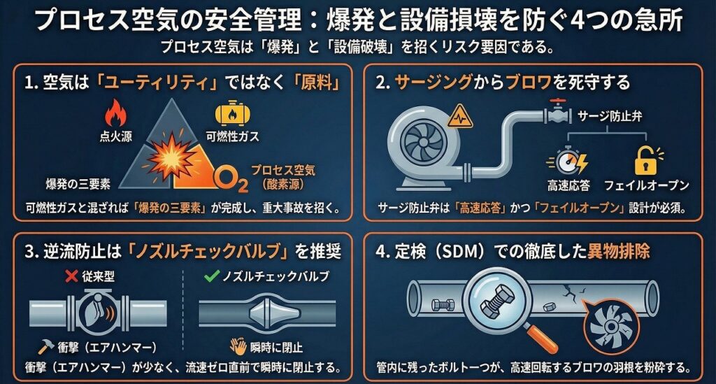
本記事では、プラントの心臓部で作動する「プロセス空気」に焦点を当てます。単なる動力源ではなく、反応原料として扱われるプロセスの空気は、一歩間違えれば大事故に直結する危険性を秘めています。
大型ブロワのサージング防止制御や、高温・高圧下における逆止弁の選定、そしてプロセス流体の逆流を防ぐための設計・保全の急所を、現場の知見に基づいて詳述します。
原料としての「空気」に向き合う
計装空気や雑用空気が「ユーティリティ(裏方)」なら、プロセス空気は「主役(原料)」です。FCC(流動接触分解装置)の触媒再生や、SRU(硫黄回収装置)の燃焼用として、文字通り反応に直接関与します。
「ただの空気が逆流したくらいで……」という油断は禁物です。可燃性のプロセス流体が存在するラインに、酸素を含んだ空気が入り込めば、そこには「爆発の三要素」が完成してしまいます。
今回は、そのリスクを設計と保全でどう封じ込めるか、深く掘り下げていきましょう。
プロセス空気の設計条件と配管仕様
プロセス空気は、大型の遠心ブロワや軸流ブロワによって供給されます。圧縮されることで温度が上昇するため、配管設計には独特の配慮が必要です。
設計圧力と設計温度
一般的なプロセス空気ラインの条件例を見てみましょう。
設計圧力: 0.3 ~ 0.6 MPaG(装置の要求による)
設計温度: 150℃ ~ 250℃(断熱圧縮による上昇)
管種: 炭素鋼鋼管(STPGやA106等)
ここで注意すべきは温度です。圧縮機直後の配管は200℃を超えることも珍しくありません。このため、熱膨張による配管応力の計算が必須となります。
また、万が一のプロセス流体逆流を想定し、反応器に近い側の配管仕様は、プロセス流体の性質(腐食性やさらに高い設計温度)に引きずられる形で格上げされるケースが多々あります。
配管径と流速
プロセス空気は大流量を扱うため、配管径は非常に大きくなります。流速の設定が不適切だと、騒音や振動、あるいは圧力損失の増大を招きます。
一般的には、常用状態で20~30 m/s程度を目安に設計されます。
ブロワの命を守る「サージング防止制御」
プロセス空気を送り出す大型ブロワにとって、最大の敵は「サージング(脈動)」です。これは、吐出側の圧力が上がりすぎたり、流量が減りすぎたりしたときに、流体が逆流と順流を繰り返して激しい振動を起こす現象です。
サージングのメカニズムと制御戦略
ブロワには「サージライン」と呼ばれる限界点があります。流量(Q)が減少し、圧力(H)が高くなると、ブロワの翼が空気を掴めなくなり、失速します。
これを防ぐのが、アンチサージコントロール(サージ防止制御)です。
基本戦略は、吐出流量が限界値に近づいた際、アンチサージ弁(放散弁またはバイパス弁)を瞬時に開き、強制的に流量を確保することです。
制御の勘所
高速応答性: サージングは数秒単位で発生するため、アンチサージ弁には極めて高い応答スピードが求められます。
フェイルオープン設計: 計装空気が喪失した際や電源が切れた際、弁は必ず「全開」にならなければなりません。ブロワを壊すくらいなら、空気を逃がして安全を確保するという思想です。
爆発防止の要諦:逆止弁(チェックバルブ)の選定基準
プロセス空気ラインにおける最大の悪夢は、ブロワの停止時にプロセス側から可燃性ガスが空気配管内に逆流することです。これを物理的に阻止するのが逆止弁の役割ですが、ここには高度な選定眼が求められます。
逆止弁の種類と使い分け
通常のユーティリティで使うようなスイング式逆止弁では、大口径・高速流のプロセス空気ラインには不十分な場合があります。
デュアルプレート式(ウェハー形): コンパクトで設置性は良いですが、急激な逆流時には衝撃(ウォーターハンマーならぬエアハンマー)が発生しやすい。
ティルティングディスク式: 圧力損失が少なく、閉止動作がスムーズです。
ノズルチェックバルブ(ノンスタム): プロセス空気の「急所」で推奨されるのはこれです。バネの力を利用して流速がゼロになる直前に閉止するため、衝撃がほとんどなく、逆流を瞬時に遮断します。
設置上の注意点
逆止弁は「水平配管」に設置するのが基本ですが、スペースの制約で垂直配管にする場合は、バネ付きのタイプを選定しなければなりません。
また、メンテナンス性を考慮して、前後には必ずアイソレーション用の手動弁を設置し、逆止弁自体の分解点検ができるスペースを確保することが設計担当者の腕の見せ所です。
定検工事(SDM)における保全の急所
定検工事でプロセス空気ラインを扱う際、監督員として絶対に外せないポイントをまとめます。
逆止弁の内部点検とシートリークテスト
「付いているから大丈夫」という思い込みが最も危険です。長期間の運転で、ディスクの軸が摩耗していたり、バネが折損していたりすることがあります。
SDMでは必ず開放し、以下の点を確認してください。
- ディスクの摺動部にカジリがないか。
- シート面にプロセス側からの付着物(触媒粉やカーボンなど)がないか。
- 可能であれば、実際に水を張る、あるいはエアをかけて逆方向の漏れ(シートリーク)を確認してください。
アンチサージ弁の作動試験(ループテスト)
ブロワ本体のオーバーホールと同様に重要なのが、制御系の点検です。
- 計装担当と連携し、インターロック試験を行います。
- 全閉から全開までのストローク時間が設計値(通常は2秒以内など非常に高速)を満たしているかを確認します。
異物混入の徹底排除
プロセス空気配管は口径が大きいため、施工中に工具やウエス、ボルトなどが内部に残りやすいものです。
これらが残ったままブロワを起動すると、高速で飛散した異物が後段の反応器のディストリビューターを詰まらせたり、最悪の場合は高速回転しているブロワのインペラ(羽根車)を直撃して大破させたりします。
管内清掃(ファイバースコープ確認)は、過剰と思えるほど念入りに行ってください。
見えないリスクを、確かな設計で封じ込める
プロセス空気は、普段はただ静かに大口径の配管を流れています。しかし、ひとたび制御を失えば、巨大なブロワを数秒で破壊し、プラント全体を危険に晒す破壊力を秘めています。
設計担当の皆さんは、単に「空気が流れるルート」を作るのではなく、「異常時にどう止めるか」という防壁を作っているのだと自負してください。
また、工事監督の皆さんは、その防壁が正しく機能するように、地味な分解点検や清掃に魂を込めてください。
「当たり前に空気が流れ、当たり前に反応が進む」
その当たり前の光景こそが、私たちの仕事の集大成です。次の工事でも、皆さんの確かな仕事で、プラントの安全を守り抜いていきましょう。
Process Air and Blower Control
This article focuses on "process air," which operates at the heart of the plant. Process air, treated not merely as a power source but as a reaction material, carries the risk of a major accident if misused.
This document details, based on practical experience, the critical aspects of preventing surging in large blowers, selecting check valves under high temperature and pressure conditions, and designing and maintaining systems to prevent backflow of process fluids.
Facing "air" as a raw material
If instrumentation air and general-purpose air are "utility" air (behind the scenes), then process air is the "main character" (raw material). It literally participates directly in reactions, such as in catalyst regeneration in FCCs (fluid catalytic cracking units) and combustion in SRUs (sulfur recovery units).
It's dangerous to be complacent and think, "It's just a little air flowing back..." If oxygen-containing air enters a line containing flammable process fluid, the "three elements of an explosion" are created.
This time, let's delve deeper into how to contain those risks through design and maintenance.
Design conditions and piping specifications for process air
Process air is supplied by large centrifugal or axial blowers. Because the temperature rises due to compression, unique considerations are required in piping design.
Design pressure and design temperature
Let's look at an example of typical process air line conditions.
Design pressure: 0.3 to 0.6 MPaG (depending on equipment requirements)
Design temperature: 150°C to 250°C (temperature rise due to adiabatic compression)
Pipe type: Carbon steel pipe (STPG, A106, etc.)
The temperature is a crucial factor here. It's not uncommon for the piping immediately after the compressor to exceed 200°C. Therefore, calculating the stress on the piping due to thermal expansion is essential.
Furthermore, in anticipation of a potential backflow of process fluid, the piping specifications closer to the reactor are often upgraded, influenced by the properties of the process fluid (corrosiveness and higher design temperatures).
Pipe diameter and flow velocity
Process air handles high flow rates, resulting in very large pipe diameters. Improper flow velocity settings can lead to increased noise, vibration, and pressure loss.
Generally, they are designed to withstand speeds of around 20-30 m/s under normal operating conditions.
"Surging prevention control" to protect the life of your blower
For large blowers that deliver process air, the biggest enemy is "surging" (pulsation). This is a phenomenon in which the fluid repeatedly reverses and reverses flow when the pressure on the discharge side becomes too high or the flow rate decreases too low, causing violent vibrations.
Surging Mechanisms and Control Strategies
A blower has a limiting point called the "surge line." When the airflow ( Q ) decreases and the pressure ( H ) increases, the blower blades lose their ability to grip the air and stall.
Q_min = f(H)
Anti-surge control is what prevents this.
The basic strategy is to instantly open the anti-surge valve (discharge valve or bypass valve) when the discharge flow rate approaches its limit, thereby forcibly maintaining the flow rate.
Key points of control
High-speed response: Since surging occurs in seconds, anti-surge valves require extremely high response speeds.
Fail-open design: In the event of a loss of instrument air or power outage, the valve must always open fully. The idea is to ensure safety by releasing air rather than damaging the blower.
The key to explosion prevention: Selection criteria for check valves
The biggest nightmare in process air lines is the backflow of flammable gases from the process side into the air piping when the blower stops. Check valves play a crucial role in physically preventing this, but this requires a high level of selection expertise.
Types and uses of check valves
Standard swing-type check valves used in utilities may be insufficient for large-diameter, high-speed process air lines.
Dual-plate type (wafer type): Compact and easy to install, but prone to generating shocks (air hammer, not water hammer) during sudden backflow.
Tilting disc type: Low pressure loss and smooth closing operation.
Nozzle check valve (non-stam): This is the recommended choice for the "critical point" of process air. It uses spring force to close just before the flow velocity becomes zero, resulting in virtually no shock and instantaneous shutoff of backflow.
Installation precautions
Check valves are typically installed in horizontal piping, but if space constraints necessitate vertical piping, a spring-loaded type must be selected.
Furthermore, considering maintainability, it is essential to install manual isolation valves at both the front and rear, and to ensure sufficient space for disassembly and inspection of the check valve itself. This is where the designer's skill comes into play.
Key points of maintenance in scheduled maintenance (SDM)
This document summarizes the essential points that supervisors must not overlook when working with process air lines during scheduled maintenance work.
Internal inspection and seat leak test of check valves
The most dangerous assumption is, "It's there, so it's okay." Over time, the disc's axle may wear down, or the spring may break.
In SDM, be sure to open it and check the following points.
Check if there is any galling on the sliding parts of the disc.
Check the sheet surface for any deposits from the process side (such as catalyst powder or carbon).
If possible, actually fill it with water or blow air into it to check for leaks in the reverse direction (sheet leaks).
Operational test (loop test) of the anti-surge valve
Just as important as overhauling the blower unit itself is inspecting the control system.
We will conduct interlock tests in coordination with the instrumentation team.
We verify that the stroke time from fully closed to fully open meets the design value (usually very fast, such as within 2 seconds).
Thorough elimination of foreign object contamination
Because process air piping has a large diameter, tools, rags, bolts, and other objects tend to get stuck inside during installation.
If these particles remain and the blower is started, the foreign matter will be scattered at high speed and clog the distributor of the downstream reactor, or in the worst case, it will directly hit the blower's impeller (blade) which is rotating at high speed and cause severe damage.
Please perform pipe cleaning (including fiberscope inspection) with excessive thoroughness.
Containing unseen risks through robust design
Process air normally flows silently through large-diameter pipes. However, once it loses control, it possesses the destructive power to destroy a massive blower in seconds and endanger the entire plant.
Those of you in charge of design should be proud that you are not simply creating a "route for air to flow," but rather building a "safety net" that will stop the flow in case of an anomaly.
Furthermore, I ask that all construction supervisors dedicate themselves wholeheartedly to the meticulous disassembly, inspection, and cleaning to ensure that the protective barrier functions correctly.
"Air flows naturally, and reactions proceed naturally."
That seemingly ordinary scene is the culmination of all our work. Let's continue to protect the safety of the plant with your reliable work in the next construction project as well.